GPIO Configuration
The RockREMOTE GPIO can be configured in the UI under the GPIO section. This section is only available on hardware revision 2. To verify your hardware revision, go to System > Hardware Revision under the System Overview section. The hardware revision number will be followed by a letter, for example 2E. If the first number is 2, then your hardware supports GPIO and will be available in firmware version v1.3.0 or greater.
RockREMOTE

Outputs are Open-Drain. Floating = Float/disconnected. Low = Shorted to 0 V.
Inputs are Active-Low with internal pull-up. High = Float/disconnected. Low = Shorted to 0 V.
| Pin | Description |
|---|---|
| 1 | ⇄ 0 V |
| 2 | ⇄ 0 V |
| 3 | ← Input 1 |
| 4 | → Output 1 |
| 5 | ← Input 2 |
| 6 | → Output 2 |
| 7 | ← Input 3 |
| 8 | → Output 3 |
| 9 | ← Input 4 |
| 10 | → Output 4 |
RockREMOTE Rugged
Serial IO
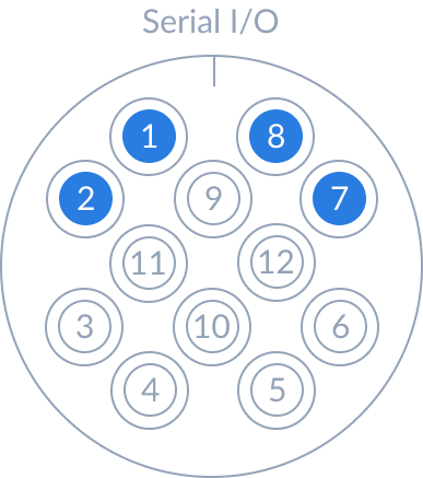
Outputs are Open-Drain. Floating = Float/disconnected. Low = Shorted to 0 V.
Inputs are Active-Low with internal pull-up. High = Float/disconnected. Low = Shorted to 0 V.
| Pin | Colour | Signal |
|---|---|---|
| 1 | Brown | Output 1 |
| 2 | Blue | Output 2 |
| 3 | White | Serial Comms |
| 4 | Green | Serial Comms |
| 5 | Yellow | Serial Comms |
| 6 | Gray | Serial Comms |
| 7 | Pink | Input 2 |
| 8 | Red | Input 1 |
| 9 | Black | Reserved |
| 10 | Orange | Sleep |
| 11 | Purple | Ground |
| 12 | Light Green | Reserved |
Serial IO colour-coding is based on the optional 12pin cable accessory.
Local UI GPIO Configuration
| RockREMOTE | RockREMOTE Rugged |
|---|---|
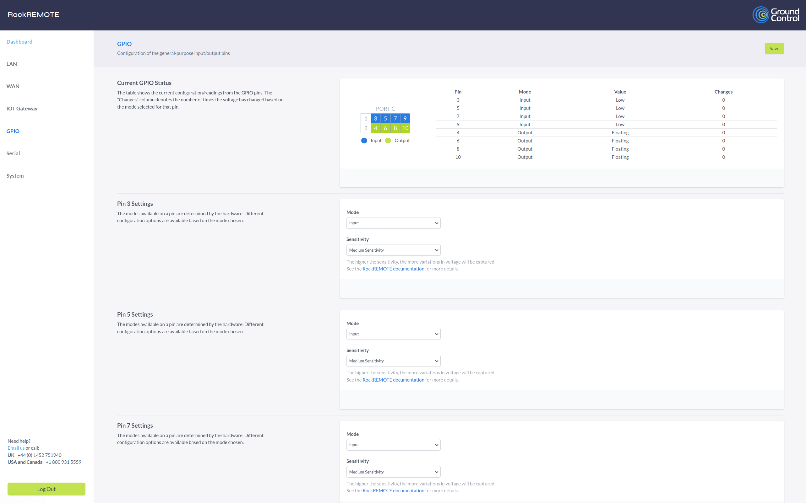 | 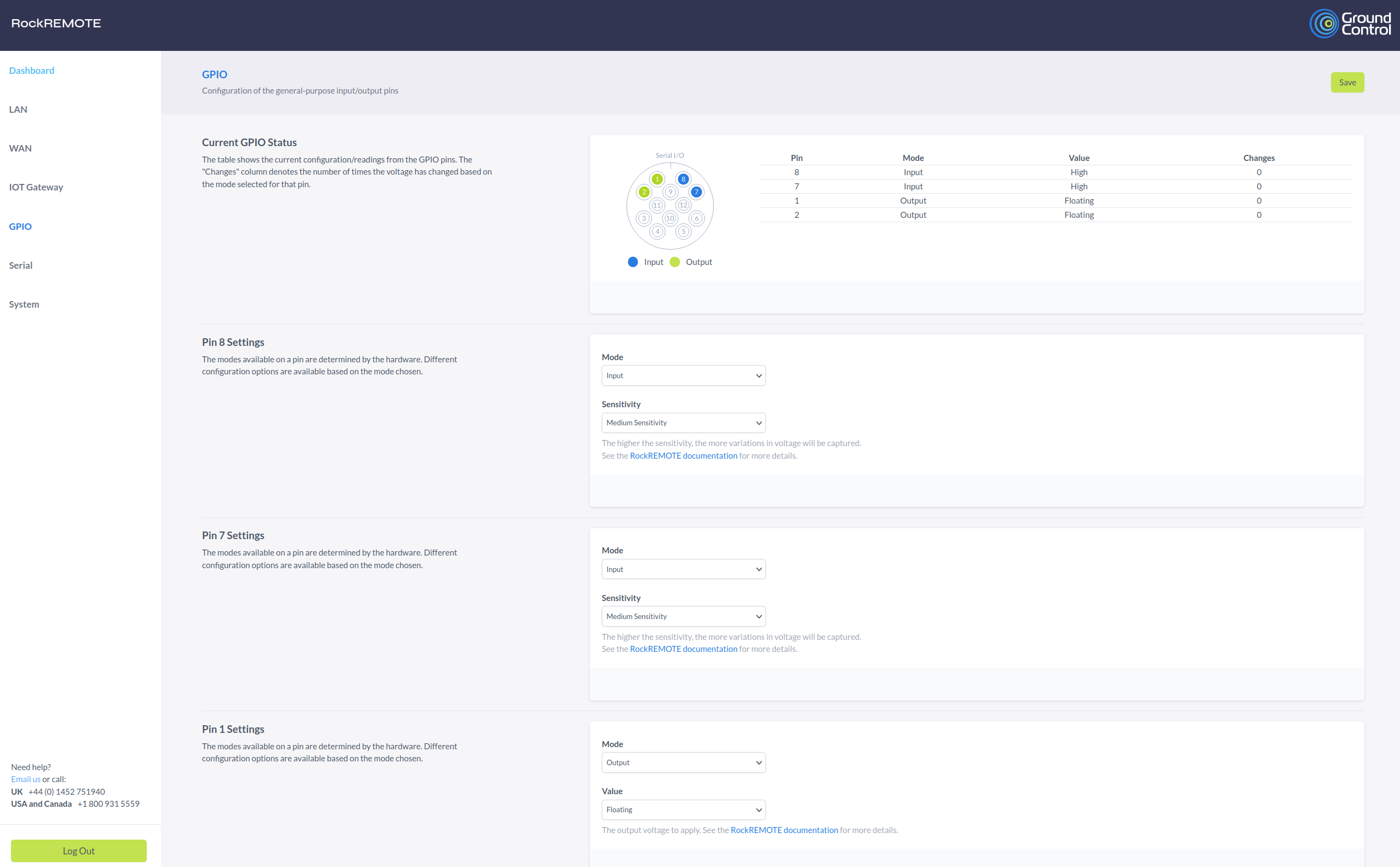 |
Current IO Status
This section displays the current states of the GPIO pins, along with a corresponding pinout diagram. The diagram will vary depending on whether you are using the RockREMOTE or the RockREMOTE Rugged.
Pin: The pin number.
Mode: The current mode of the GPIO pin.
Value: The current value of the GPIO pin.
Changes: The number of times the GPIO pin has changed state since the device was booted or the mode of the pin was changed. This value only increments for input pins that are configured in a interrupt mode.
IO Settings
This section lists all of the GPIO pins and their current settings. The list starts with the inputs, followed by the outputs. When you apply these settings, they will be saved in the RockREMOTE's persistent configuration and will be re-applied when the device boots. During power-on and boot-up, the GPIO states are undefined, so they may not be usable while the RockREMOTE is booting.
Input settings
| Mode | Description |
|---|---|
| Input | The default mode. No input interrupts are enabled. The states in the UI will update depending on the input. |
| Input - Voltage Rising | Rising edge interrupt. When the input sees a rising edge, it will increment the Changes counter for that input. If GPIO unsolicited events are enabled, the GPIO state will be sent to Cloudloop Device Manager. |
| Input - Voltage Falling | Falling edge interrupt. Same as above, but for a falling edge. |
| Input - Voltage Change | Change edge interrupt. Same as above, but for any edge detection. |
| Sensitivity | Description |
|---|---|
| High | A change in state is detected if it has been stable for 50 milliseconds. |
| Medium | A change in state is detected if it has been stable for 100 milliseconds. |
| Low | A change in state is detected if it has been stable for 200 milliseconds. |
Output settings
| Mode | Description |
|---|---|
| Output | The only mode supported. The output can be set to Floating or Low. |
| Value | Description |
|---|---|
| Floating | The output is not connected to anything. |
| Low | The output is shorted to 0 V. |